We will be closed for the holidays from Friday, December 20th, 2024 through Sunday, January 5th, 2025.
Our offices reopen Monday, January 6th, 2025 at 6:30 AM Pacific Time.
Thank you for your continued business and we look forward to serving you in the new year!

ETACH2 HIGH SPEED ENCODER TO ANALOG TACHOMETER

ETACH2 Features

  • 0 to 4.095V and 0 to 10V or 4.095V and 10V output
  • Max. input frequency adjustable from 0.03Hz to 12.7MHz
  • 7kHz update rate
  • Isolated SPDT relay output for overspeed or underspeed
  • Droop free
  • No cogging or ripple at low speeds 12-bit analog resolution
  • Digital encoder direction bit output
  • Programmable input frequency ranges, frequency limits and output ranges
  • DIN rail mounting available
  • 0 to +70C operating temperature

See more info below

Configure the ETACH2

The ETACH2 is no longer available for purchase.

ETACH2 Product Description

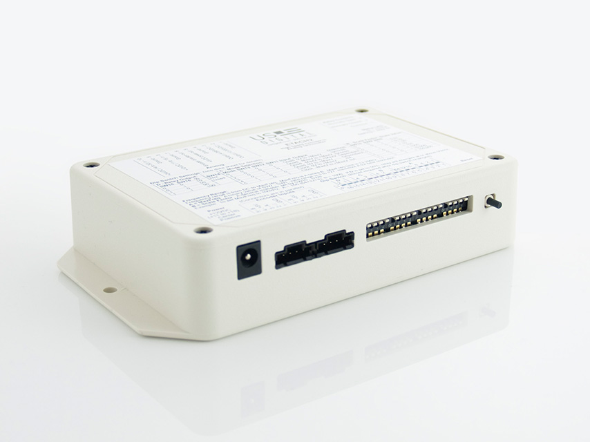
The ETACH2 is a high-performance analog tachometer that converts incremental encoder signals into a stable analog voltage. The ETACH2 is fast enough to be used in a velocity or servo control loop, typically requiring a tachometer generator. The ETACH2 has a wide programmable full-scale frequency range and does not suffer from the low-speed droop and ripple typically found with traditional analog tachometer generators. Incremental quadrature encoder signals are digitally converted to provide either positive or negative voltages; positive output voltages are provided when the signals are rotated in a positive direction, and negative voltages are provided when the direction is reversed. You can also select the output to provide zero to maximum positive voltage output. A TTL digital direction bit is provided.

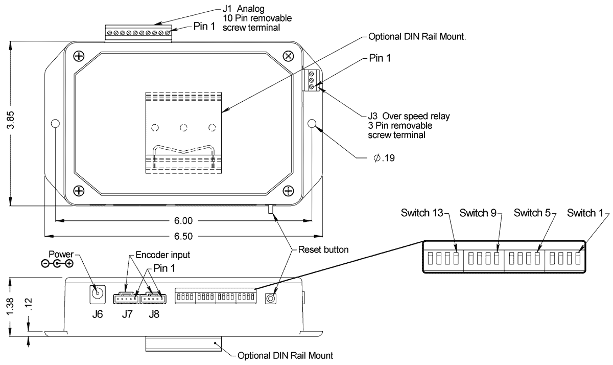
The ETACH2 is programmed by an array of DIP switches that determine the operating frequency range and mode of operation. Two encoder connectors are provided in parallel to make it convenient to loop the encoder signals through the ETACH2. This allows the signals to be easily applied elsewhere in a control loop. An isolated SPDT relay output, accessed through a pluggable 3-position screw terminal, provides a speed switch output that you will activate if the input frequency reaches an over speed limit programmed by the DIP switches. The minimum on time for the relay is 0.5 seconds, even if the output is momentarily triggered.

An internal switching regulator provides internal power and supplies 5VDC to the external encoder. The analog output voltage, TTL direction, and ground are accessed on a 10-pin pluggable screw terminal. The terminal also provides an alternate way of powering the ETACH2 instead of using the mini power jack.

Product Specifications

ELECTRICAL

Unless otherwise specified, all accuracy measurements assume 100kHz and within temperature range 0 to 70 C.

PARAMETER MIN. TYP. MAX. UNITS NOTES
Quadrature Cycle Input Frequency 0 - 8.0 MHz 1 quadrature cycle = 4 quadrature states.
Non-quadrature Input Frequency 0 - 12.7 MHz  
Input Supply Voltage 11
14
12
24
18
30
Volts
Volts
Through J6 or J1 pin-8.
Through J1 pin-10.
Supply Current - 12V Input -
-
75
200
-
-
mA
mA
No encoder load.
250mA encoder load.
Supply Current - 24V Input -
-
46
103
-
-
mA
mA
No encoder load.
250mA encoder load.
Relay Contact Rating - - 2.0 A 24VDC / 125VAC
Relay Dielectric Strength 500
500
-
-
-
-
VAC
VAC
Open contact.
Contact to coil.
Relay Contact Resistance - - 0.1 Ohms Contact resistance.
Direction Output Bit - Logic Low - - 0.4 Volts 8mA (sinking current).
Direction Output Bit - Logic High 2.4 - - Volts -4mA (sourcing current).
Full Scale Output Error -0.5
-1.5
0
0.25
0.5
1.5
% full scale
% full scale
For 4.095V output mode.
For 10V output mode.
Analog Output Load Impedance 680 - - Ohms  
Voltage Out to Encoder 4.8 5.0 5.2 Volts Under 100mA load.
Output Voltage Update Rate  - 7.0  - kHz  
Encoder Current - - 250 mA +5V power for external encoder.
Quadrature Encoder Inputs - Logic Low* 0 0.4 0.8 Volts  
Quadrature Encoder Inputs - Logic High* 2.0 5.0 5.75 Volts  

* Diode clamped to ground and +5V, 10K pullup to +5V.

DIP SWITCH SETTINGS

The ETACH2is configured by an array of DIP switches. These switches are numbered from right to left. Complete explanations and switch definitions can be found below.

  • Switches 1 through 10 set the frequency range.
  • Switches 11 through 13 set the operation mode.
  • Switch 14 is not used.
  • Switches 15 and 16 set the relay output as a function of % of full range speed.

FREQUENCY RANGE

DIP switches 1 through 7 set the base frequency range in Hz or quadrature cycles per second as a binary representation of the switches. DIP switches 8, 9 and 10 provide a decimal scaling factor to the value of switches 1 and 7.

The frequency of the encoder output signal that is required to reach the full scale voltage of the ETACH2 is determined by the following equation. Please note: 1 = Up Position = Switch Off, 0 = Down Position = Switch On.

BF * SF = Encoder Frequency.

BF (Base Frequency) is determined by setting switches SW1 though SW7 (see table 1 in DIP Switch Definitions). The sum of the values assigned to the switches should be between 3 and 127. To maximize the resolution of the ETACH2 choose the largest possible value of BF that will satisfy your configuration operating requirements.

SF (Scale Factor) is determined by setting switches SW8 though SW10. Scale factors can be selected with ranges from 0.01 to 100,000 (see table 2 in DIP Switch Definitions).

Example 1: Encoder Frequency = 100kHz

Set BF to 100 (100 = 64 + 32 + 4; switches 7, 6 and 3 should be set to 1). Set SF to 1000 (SW10=1, SW9=0 and SW8=1).

BF * SF = Encoder Frequency
100 * 1000 = 100 KHz.

Example 2: Encoder Frequency = 200 kHz

Set BF to 20 (20 = 16 + 4; switches 5, 3 should be set to 1). Set SF to 10000 (SW10=1, SW9=1 and SW8=0).

BF * SF = Encoder Frequency
20 * 10000 = 200 kHz
MODE SELECTION

Mode 0:

Quadrature encoder input. Output voltage range is Zero Volts to +Maximum Volts.
Output is independent upon direction of encoder rotation.

  • Zero Volts represents zero encoder frequency.
  • +Maximum Volts represents maximum encoder frequency.

Mode 1:

Quadrature encoder input. Output voltage range is -Maximum Volts to +Maximum Volts.
Output is independent of direction of encoder rotation.

  • -Maximum Volts represents zero encoder frequency.
  • Zero Volts represents middle encoder frequency.
  • +Maximum Volts represents maximum encoder frequency.

Mode 2:

Quadrature encoder input. Output voltage range is -Maximum Volts to +Maximum Volts.
Output is dependent upon direction of encoder rotation.

  • -Maximum Volts represents maximum encoder frequency in one direction.
  • Zero Volts represents zero encoder frequency.
  • +Maximum Volts represents maximum encoder frequency in the opposite direction.

Mode 3:

Quadrature encoder input. Output voltage range is Zero Volts to +Maximum Volts.
Output is dependent upon direction of encoder rotation.

  • Zero Volts represents maximum encoder frequency in one direction.
  • 1/2 maximum Volts represents zero encoder frequency.
  • +Maximum Volts represents maximum encoder frequency in the opposite direction.

Mode 4:

Single channel non-quadurature frequency input. Output voltage range is Zero Volts to +Maximum Volts.

  • Zero Volts represents zero frequency input.
  • +Maximum Volts represents maximum frequency input.

Mode 5:

Single channel non-quadrature frequency input.
Output voltage range is -Maximum Volts to +Maximum Volts.

  • -Maximum Volts represents zero frequency input.
  • Zero Volts represents 1/2 maximum frequency input.
  • +Maximum Volts represents maximum frequency input.

Mode 6, Mode 7:

Not used. If switch is configured to this mode, ETACH2 operation defaults to Mode 4.

RELAY OUTPUT

DIP switches 15 and 16 are used to program the desired percent of full scale frequency. The ETACH2 has an isolated single pole double throw relay output contact closure that may be configured as an over speed limit switch. The relay closure may be configured as a percentage of the maximum full-scale frequency. The relay will activate at or above the programmed frequency. Once triggered, the relay will stay on for at least 0.5 seconds even if the frequency drops below the threshold.

DIP SWITCH DEFINITIONS

BASE FREQUENCY (SW1 - SW7):

MODE SW13
SW1 1
SW2 2
SW3 4
SW4 8
SW5 16
SW6 32
SW7 64

SCALING FACTOR (SW8 - SW10):

SCALING FACTOR = SCALING VALUE
SW10 SW9 SW8  
Down Down Down = 0.01
Down Down Up = 0.10
Down Up Down = 1.00
Down Up Up = 10
Up Down Down = 100
Up Down Up = 1,000
Up Up Down = 10,000
Up Up Up = 100,000

OPERATION MODE (SW11 - SW13):

MODE SW13 SW12 SW11
0 Down Down Down
1 Down Down Up
2 Down Up Down
3 Down Up Up
4 Up Down Down
5 Up Down Up

RELAY OUTPUT (SW15 - SW16):

SW16 SW15 % OF FULL SCALE
Down Down 10%
Down Up 50%
Up Down 90%
Up Up 100%

PIN-OUTS

J1 Analog Connector:

PIN DESCRIPTION
1 Ground
2 Output signal (0 to +10VDC)
   or (10VDC)
3 Output signal (0 to +4.095VDC)
   or (4.095VDC)
4 Ground
5 +5VDC power out
6 Encoder direction out
7 Ground
8 +12VDC in* (+11 to +18)
9 Ground
10 +24VDC in* (+14 to +30)

* Connect only one power source.

J3 Relay Contacts Connector:

PIN DESCRIPTION
1 Common
2 Normally Closed
3 Normally Open

J7 & J8 Encoder Connector:

PIN DESCRIPTION
1 Ground
2 Index
3 A channel
4 +5VDC power
5 B channel

PRODUCT CHANGE NOTIFICATIONS

Title Date Description Download
PCN 1011 9/21/2011 The AD2B, AD4B, AD7, EADAPT, EDAC2, EDIVIDE, EPOT, EQUAD, ESUM, ESWITCH, ETACH2, SEI-USB, USB-232 currently utilizes a printed thermal transfer label. This label will no longer be used and will be replaced by laser marking directly onto the housing of the product. The purpose for this change is to create a more durable solution and eliminate the possibility of the label being inadvertently removed from the housing. Download
EOL ETACH2 - PCN 1026 6/17/2013 This PCN is a formal notification that US Digital is discontinuing the ETACH2. Download

Additional Information

Product Notes

  • US Digital® warrants its products against defects in materials and workmanship for two years. See complete warranty for details.

Datasheets


Feedback

US Digital's mission is a commitment to quality and constant improvement. If you find an error to a product on this page, please let us know!

Compare Items (Max 3):