CE Marking: Starting July 22nd, 2014, some US Digital products will contain the CE Marking. The
USB4 will not contain a CE Marking and will
not be available for shipping to CE Mark required countries (for example, all countries within the European Union (EU))
after July 10th, 2014. See the
Product Change Notification PCN 4464 for more information, or contact a US Digital representative at
sales@usdigital.com.
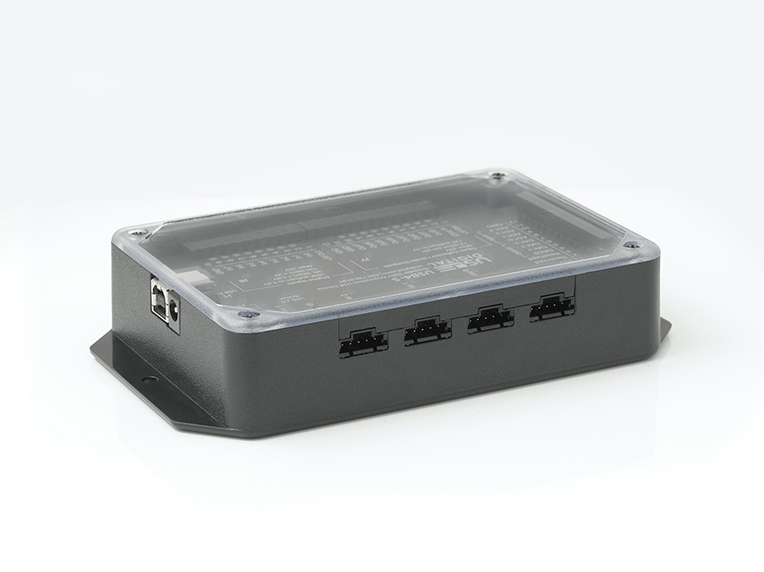
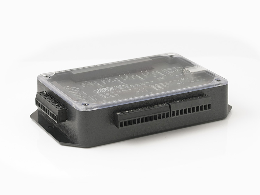
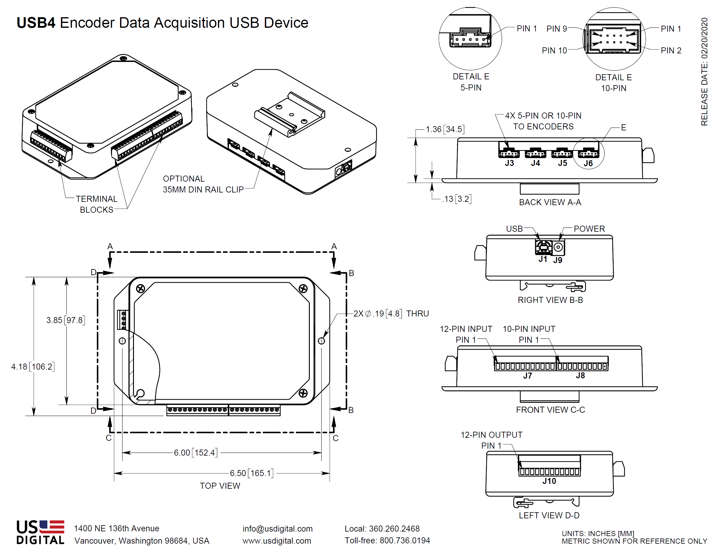
USB4 Product Description
The USB4 is a data acquisition device designed to record data from 4 incremental encoders, 8 digital inputs, and 4 analog input channels. In addition, the USB4 provides 8 digital outputs and 4 analog output channels. The 8 digital outputs also have a latching emergency stop (E-Stop) input. When the E-Stop input is activated, the 8 digital outputs will turn off immediately. The analog input/output channels provide 12-bit data conversions at rates up to 44 kHz per channel. All communication between the USB4 and the host PC is sent over a USB interface. To handle continuous streaming of data over USB to the host PC, the USB4 has a 32 Mbyte FIFO buffer.
The digital input port can handle input logic levels from +3V to +25V, and the digital output port has open-drain MOSFET outputs to switch up to 1A at +25V. The range of the analog input/output channels is 0V to +5V. Four independent incremental encoder interfaces are implemented in hardware on the USB4. Each encoder channel has a 24-bit up/down counter that is easily reconfigured for various counting modes such as modulo-N, non-recycle, range-limit, and normal counter mode. You can select quadrature input modes of x1, x2, x4, clock/direction, and indexing modes. Each encoder channel can measure the pulse width and pulse period of its "A" input while simultaneously decoding the quadrature state. This feature allows RPM speed measurements to be made from the encoder input or interfacing to sensors with PWM (pulse width modulated) outputs.
The USB4 can capture data once per clock cycle of a user-programmable 32-bit clock generator or on every rising or falling edge of the input port pins. Data capture can be programmed to run continuously or to start only when certain conditions are met, such as the encoder count matching a certain value or if there is encoder movement in a certain direction. Encoder events can also output on the output port to trigger external devices. You can set trigger conditions for the analog input and PWM input channels; in addition, the USB4 can be configured to have the input port pins serve as a trigger to start data acquisition. The input port triggering allows the user to form the final trigger from a combination of conditions on the input port with up to 2 levels of triggering.
Software and documentation needed to use the USB4 are available on the US Digital website. A PC demo application allows the user to configure and explore various features of the USB4 using a graphical user interface. A library with a detailed Application Programming Interface is included so users can develop their own applications. US Digital provides several examples that demonstrate how to use the FIFO, log data, etc. For users that prefer lower-level control, a documented register-based interface is provided so you can configure the USB4's internal registers at the bit level.